Custom Copper Busbar
Celestix Industries supplies custom copper busbars manufactured to customer drawings, samples, and technical requirements for electrical power distribution, interconnection, grounding, and bonding applications. A copper busbar provides a low-impedance conductive path between electrical components and may be used in switchgear, controlgear, battery systems, converters, industrial equipment, renewable-energy systems, EV charging equipment, and earthing assemblies.
Whether specified as a copper busbar, bus bar copper, Cu busbar, copper flat busbar, or industrial copper conductor, the manufacturing requirement extends beyond conductor cross-section. Material, geometry, holes, bends, contact surfaces, joints, plating, insulation, mounting, spacing, and operating conditions can all affect the finished assembly.
For buyers and engineers, the important point is that a busbar should be specified around its actual electrical, thermal, and mechanical function, not current rating alone.
Key Features
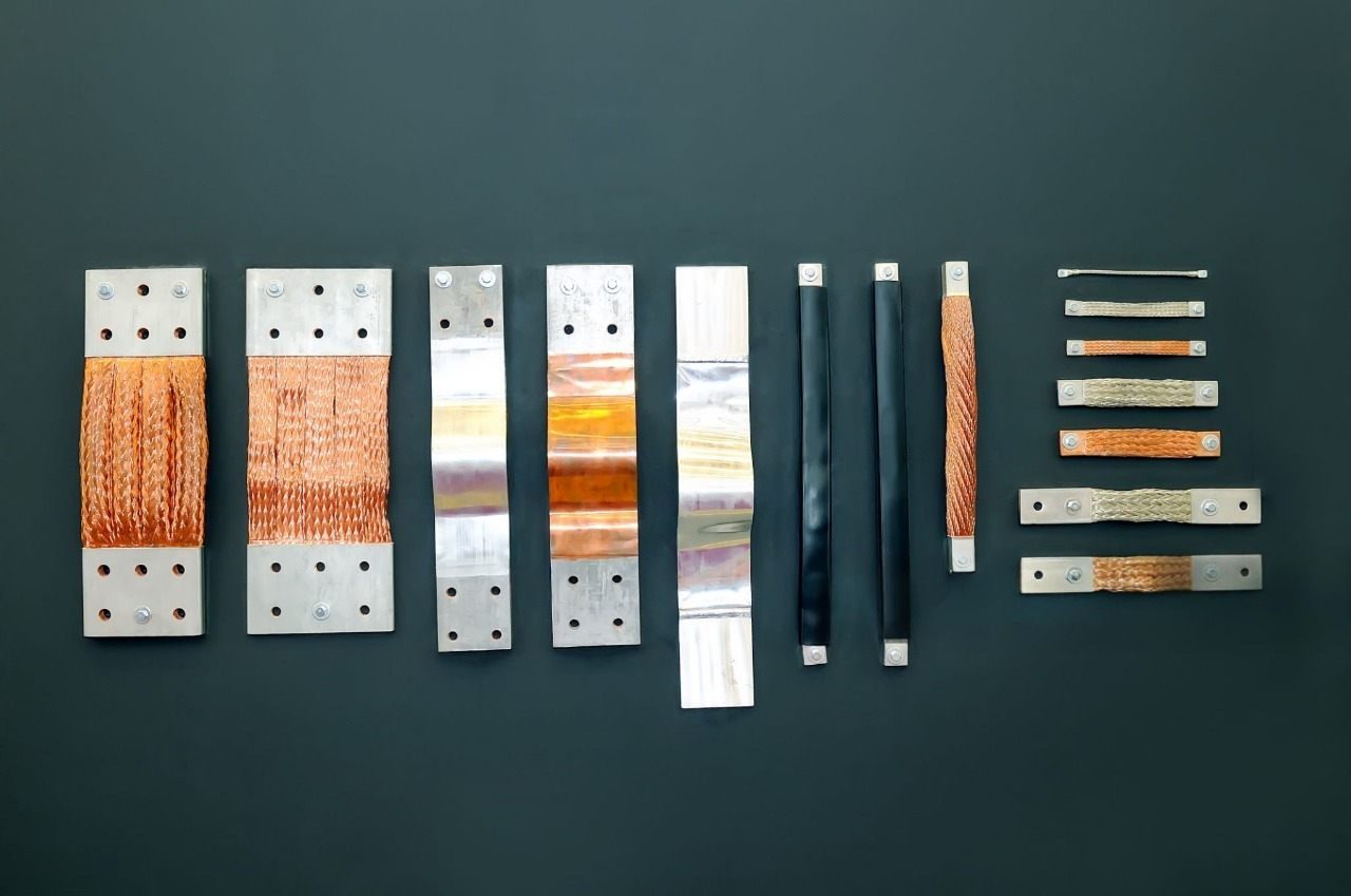
Custom busbars can range from a simple solid copper bus bar or rectangular copper busbar to a formed, drilled, punched, machined, plated, or insulated conductor.
Custom length, width, thickness, and geometry
Flat and formed copper busbar configurations
Straight and bent copper busbar designs
Custom holes, slots, and terminal patterns
Defined contact pads and mating surfaces
Bare or plated copper busbar specifications
Tin, silver, or nickel plating where specified
Insulated copper busbar configurations where required
Material grade and temper defined by the application
Grounding, protective-earth, terminal, and distribution bars
AC and DC conductor applications
Drawing-defined dimensional and inspection requirements
The conductor is only one part of the electrical system. Joints, supports, insulation, enclosure conditions, ventilation, and protective devices should also be considered when defining the finished busbar. In assemblies that combine rigid conductors with flexible electrical connections, related cable assemblies, custom cable assemblies, and wiring harnesses may form part of the overall electrical system.
Custom Options
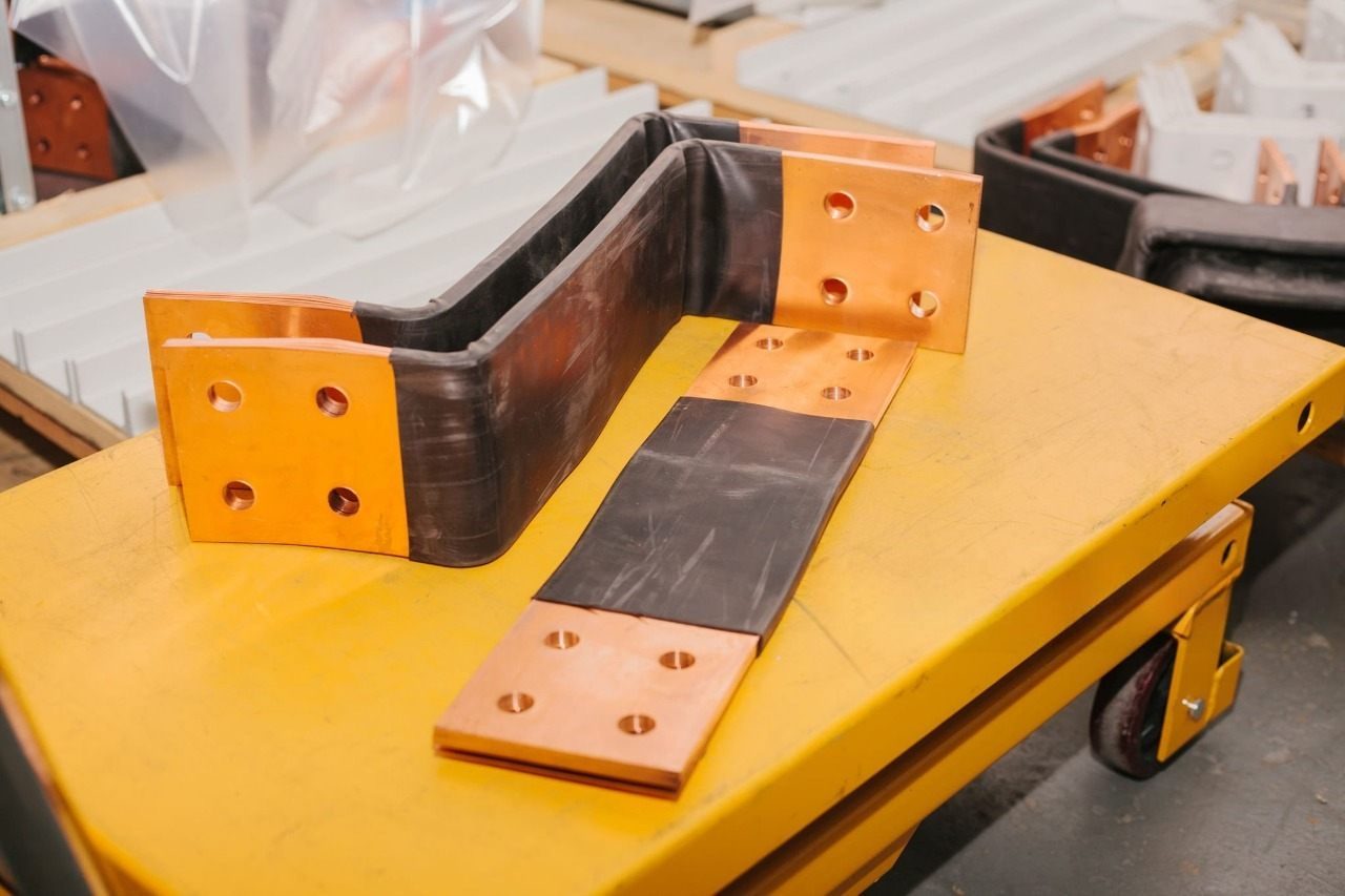
A custom copper busbar can range from a flat conductor with terminal holes to a multi-plane component incorporating bends, machined connection areas, plating, masking, and insulation.
Custom requirements may include:
Length, width, and thickness
Flat, straight, or multi-plane profiles
Custom bent copper busbar geometry
Bend direction and angle
Custom punched copper busbar hole patterns
Drilled holes and mounting features
Machined slots or connection features
Terminal and contact-pad geometry
Edge and burr requirements
Flatness and parallelism
Copper grade and temper
Bare or plated contact areas
Selective plating and masking
Insulation where required
Identification and marking
Dimensions such as terminal-hole position, contact-pad flatness, bend-to-hole location, phase spacing, and device-terminal alignment deserve particular attention when they directly affect assembly or electrical function.
Where busbars connect to cable-based systems, the interface may also need to coordinate with electrical connectors, cable terminals, and the surrounding wiring architecture.
Manufacturing
Copper busbar fabrication can involve profile cutting, hole generation, forming, machining, deburring, cleaning, surface treatment, inspection, and packaging. The manufacturing route depends on the specified copper grade and temper, thickness, geometry, quantity, tolerances, finish, and contact requirements.
Busbars are often one metal component within a larger equipment assembly. Where the project also involves fabricated enclosures, panels, brackets, mounting parts, or other formed components, buyers can review Celestix Industries' sheet metal manufacturing capabilities alongside the busbar requirement.
Manufacturing Steps
A typical custom copper busbar manufacturing sequence may include:
Material Review: Confirm the specified copper grade, temper, dimensions, and material requirements before production.
Cutting & Blanking: Cut copper bar or flat stock to the required profile using a process appropriate to the geometry and material.
Hole Making & Machining: Produce terminal holes, mounting holes, slots, pockets, tapped features, and other drawing-defined geometry by punching, drilling, milling, or machining as appropriate.
Bending & Forming: Form straight blanks into bent or multi-plane configurations while controlling bend angle, bend-to-hole relationships, springback, twist, and terminal alignment.
Deburring & Edge Finishing: Remove burrs and control edges that could interfere with electrical contact, reduce clearance, damage insulation, or introduce conductive debris.
Cleaning: Remove fabrication oils, particles, fingerprints, residues, and other contamination before finishing or assembly.
Plating or Insulation: Apply tin, silver, nickel, selective plating, masking, or insulation where specified by the drawing or application.
Final Inspection: Verify drawing-defined dimensions and relevant characteristics such as hole position, formed geometry, flatness, contact surfaces, burr condition, plating, masking, and insulation.
Marking & Packaging: Apply specified identification and package finished busbars to protect geometry, surfaces, plating, and critical contact areas during handling and shipment.
Depending on the drawing, copper busbar fabrication services may therefore involve shearing, copper busbar punching, copper busbar laser cutting, waterjet cutting, sawing, copper busbar drilling, copper busbar machining, copper busbar milling, copper busbar tapping, bending, deburring, cleaning, plating, and insulation.
A fabricated copper busbar may consequently be a drilled copper busbar, punched copper busbar, machined copper busbar, or CNC machined copper busbar depending on its manufacturing requirements.
Busbar Bending
Copper busbar bending depends on material temper, thickness, bend radius, width, grain direction, tooling, springback, and nearby features. Poorly matched geometry can contribute to cracking, twist, hole distortion, or loss of local flatness.
For this reason, bending copper busbar stock should not rely on a universal bend-radius assumption. A custom bent copper busbar may also require control of bend-to-hole dimensions and terminal alignment to maintain assembly fit.
Burr and edge condition are functional requirements, not simply cosmetic details. Burrs can interfere with contact surfaces, reduce electrical clearance, damage insulation, or introduce conductive debris into an assembly.
Materials
Material selection affects conductivity, forming behavior, mechanical stability, joining, operating conditions, and cost. An electrolytic copper busbar should therefore be specified by actual grade and temper rather than treating all conductive copper as interchangeable.
Relevant materials include:
C11000 / ETP copper: Electrolytic tough pitch copper combines high electrical and thermal conductivity with broad availability and useful fabrication characteristics.
C10100 copper: Oxygen-free copper may be selected for specialized purity, vacuum, cryogenic, or processing requirements.
OFHC copper: Oxygen-free high-conductivity terminology may appear in sourcing specifications, but the exact grade and material requirements should still be defined.
Silver-bearing copper: May be considered where retention of mechanical properties at elevated temperatures is important.
Deoxidized copper: May suit particular joining requirements, although residual phosphorus generally reduces electrical conductivity.
Terms such as HDHC copper busbar and HDHC tinned copper busbar may also appear in commercial sourcing terminology. Abbreviations should not replace a complete material specification. Buyers should define the required copper grade, conductivity, temper, dimensions, and applicable material standard.
ASTM B187/B187M covers copper conductor bar, rod, and shapes for electrical bus applications. Projects that combine rigid conductors with flexible copper conductors may also involve raw copper wire, depending on the equipment design.
Finishes
Copper busbars may be supplied bare or with a surface treatment specified around the contact interface, operating environment, joining method, storage requirements, and mating materials.
Common specifications may include:
Tin plated copper bus bar
Tin plated copper bar
Tin plated copper busbar
Tin coated copper busbar
Copper tinned busbar
Silver plated copper bus bar
Silver plated copper busbar
Nickel plated copper bus bar
Nickel plated copper busbar
Selectively plated contact areas
Bare copper
Insulation where specified
A tin plated copper busbar may be selected for oxidation protection, solderability, storage protection, terminal compatibility, or suitable interface behavior. Silver plating may be specified for particular high-current contact applications, while nickel plating may be considered where elevated-temperature behavior, corrosion resistance, wear resistance, or a diffusion barrier is required.
The coating name alone may not be a complete plating specification. Where coating performance matters, requirements may also need to define plating thickness, underplate, masking, adhesion, and inspection.
For an insulated copper busbar, the insulation system should be selected around the required dielectric, temperature, tracking, environmental, edge-coverage, and assembly conditions. Assemblies using flexible insulated conductors may also incorporate PVC wire, silicone wire, or application-specific cable assemblies.
Configurations
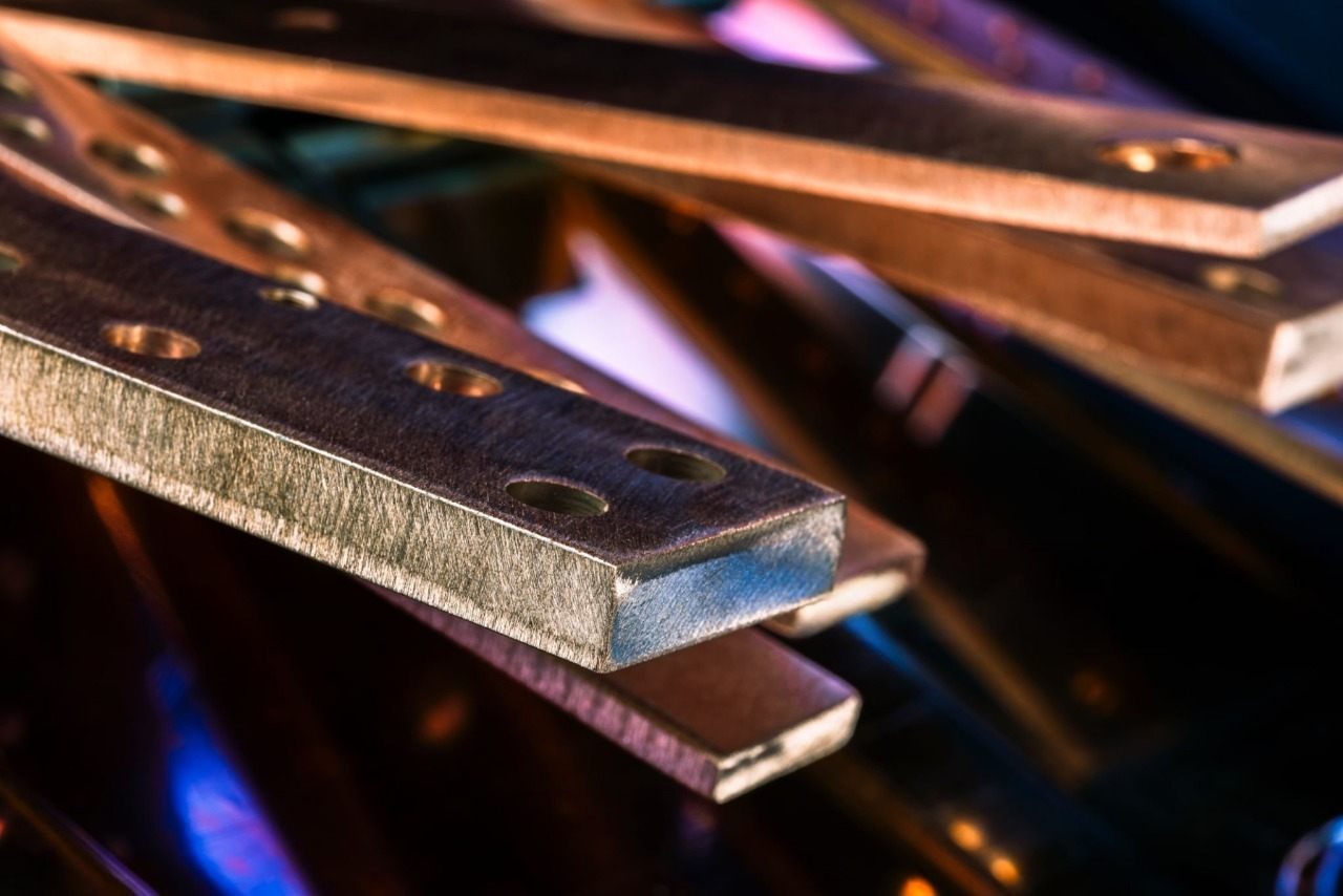
Copper busbar construction should reflect the available space, current path, connection arrangement, cooling, mechanical support, and electrical requirements.
Solid copper busbar
Copper flat busbar
Flat copper busbar
Rectangular copper busbar
Straight connection bars
Bent copper busbar
Multi-plane formed conductors
Multiple parallel bars
Phase and neutral bars
Protective-earth and grounding bars
Copper links and jumpers
Terminal and distribution bars
Battery interconnects
DC conductors
Converter and inverter connections
Insulated solid conductors
Laminated and flexible busbars
Different busbar constructions should not be assumed to have interchangeable electrical or thermal performance. Geometry, spacing, joints, installation conditions, and cooling can change how a conductor performs.
Where movement, vibration, or misalignment makes a rigid connection unsuitable, braided cable assemblies may be relevant alongside rigid busbars.
Earthing Accessories
Copper busbars also have an important role in earthing accessories and protective bonding systems. In these applications, the busbar provides a common conductive connection point for protective-earth conductors, bonding conductors, equipment grounding connections, or multiple earth termination points.
A copper earth bar may be incorporated into electrical panels, switchgear, control cabinets, industrial equipment, power-distribution assemblies, and related electrical installations. Depending on the design, multiple drilled or punched connection positions allow grounding conductors or equipment bonds to terminate on a common conductor.
Typical earthing-related configurations may include:
Protective-earth bars
Grounding busbars
Equipment bonding bars
Earth terminal bars
Common grounding points within electrical assemblies
Neutral and earth bars where separately designed for the system
Drilled or punched bars with multiple termination points
Custom bars for enclosure, panel, or equipment mounting
Material conductivity is only one consideration. Hole spacing, terminal arrangement, contact condition, mounting method, fastener access, corrosion conditions, and the required fault-current path can all influence the design.
An earthing busbar may be required to carry fault current rather than normal continuous operating current. Its electrical requirements should therefore be established from the grounding system and applicable equipment requirements rather than from a generic continuous-current value.
Bare copper may be appropriate for some grounding applications, while tin plating or another specified surface treatment may be used where contact or environmental conditions require it. Plating, hardware, and mating materials should be considered together when defining the connection interface.
For custom earthing accessories, buyers should provide the required bar dimensions, copper grade, number and size of termination holes, hole spacing, mounting arrangement, finish, hardware requirements, and applicable fault-current requirements.
Celestix also manufactures related electrical metal components represented in its plug pin socket, industrial plug pin socket, and power cord brass plug pin product categories.
Applications
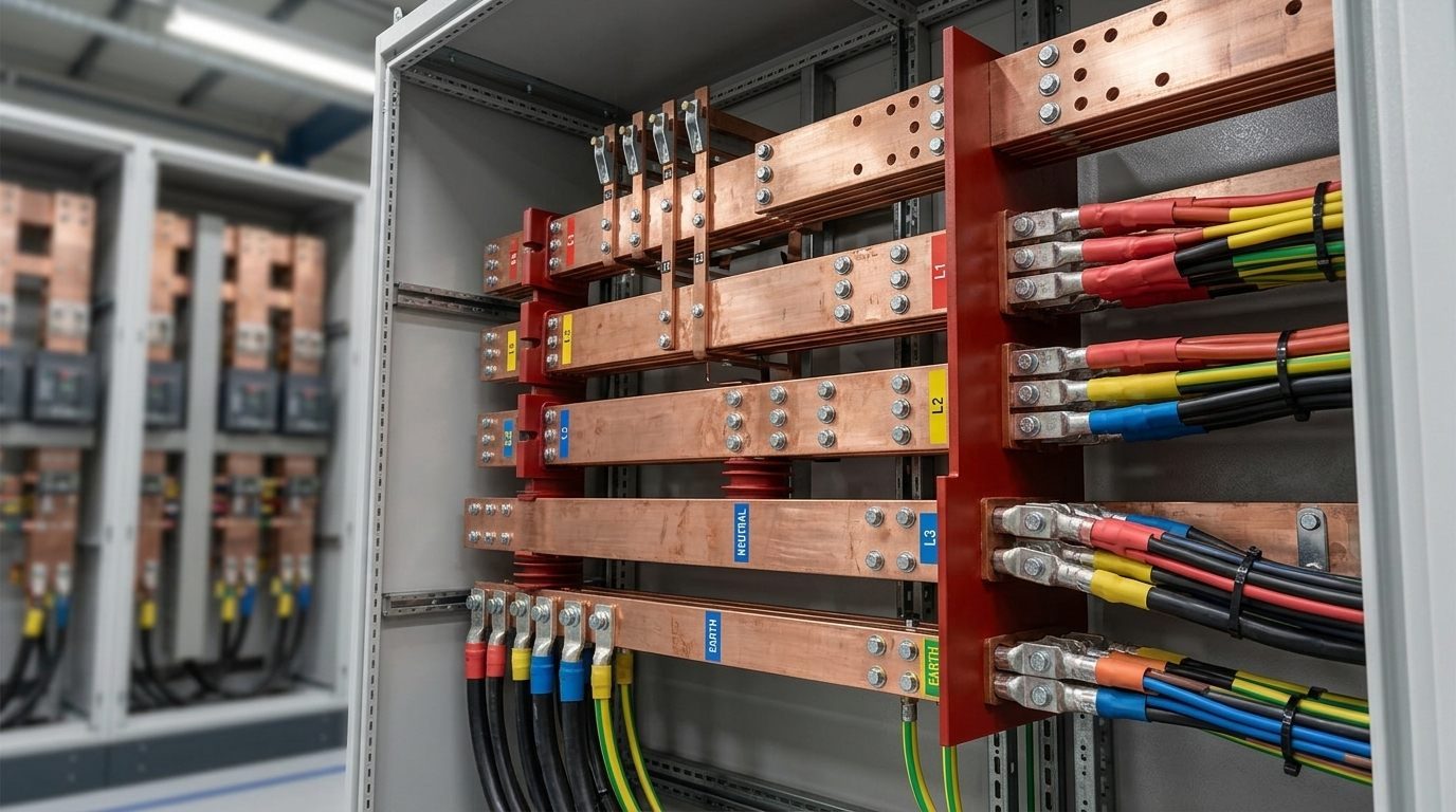
An OEM copper busbar can collect, distribute, ground, bond, or transfer electrical power while fitting the required equipment layout.
Typical applications include:
Low-voltage switchgear
Controlgear assemblies
Power-distribution equipment
Electrical panels and cabinets
Earthing and protective-earth assemblies
Equipment grounding and bonding
Transformer connections
Battery and energy-storage systems
Converter and inverter assemblies
DC-link connections
EV charging busbar applications
Industrial machinery
Renewable-energy equipment
Transportation electrical systems
High-current electrical equipment
Battery & Energy Storage
Battery and energy-storage equipment can combine rigid copper interconnects with flexible high-current cable connections. Related Celestix categories include battery cables and UPS battery cable assemblies.
Renewable Energy
Renewable-energy systems may combine copper busbars with solar cable assemblies and MC4 connectors, depending on the system architecture.
Industrial Equipment
Industrial electrical assemblies may combine busbars with industrial cable assemblies, industrial wiring harnesses, and cable harnesses.
Power Generation
Power-distribution and generation equipment may use rigid conductors alongside power-generation wiring harnesses and related cable assemblies. Test and power-loading equipment may also involve load-bank wiring harnesses.
Data Centers
High-current DC and power-distribution systems are increasingly relevant to data-center equipment. Where the system also requires cable-based interconnections, Celestix has a dedicated data-center wiring harness category.
Application context is essential. The same conductor geometry can behave differently when installed in open air, inside an enclosure, beside other conductors, or close to heat-generating equipment.
Design Factors
Current Rating
A requirement for a 200 amp copper bus bar, 400 amp copper bus bar, or 600 amp copper bus bar identifies a target current, but amperage alone does not define the required conductor size.
Temperature rise can depend on:
RMS current and AC/DC operation
Harmonic content
Copper resistance at operating temperature
Conductor geometry
Joint resistance
Ambient temperature
Enclosure and ventilation
Bar orientation and spacing
Adjacent heat sources
Duty cycle and cooling
Current density can provide an initial comparison, but it is not a universal ampacity criterion. A 200 A, 400 A, or 600 A copper busbar should therefore be sized and validated for its actual installation and operating conditions.
Electrical Performance
Busbar resistance contributes to voltage drop and power loss, while system resistance also includes joints, terminals, contacts, and other interfaces.
For AC applications, skin effect, proximity effect, harmonics, conductor spacing, orientation, frequency, and return-path geometry can increase effective resistance and influence performance.
Where a busbar interfaces with flexible conductors, cable terminations and connected assemblies should also be considered as part of the complete current path. Related options include custom cable assemblies, industrial cable assemblies, and connectors.
Short-Circuit Loads
Busbars may need to withstand both thermal and mechanical effects during fault conditions. Relevant design inputs can include short-time current, fault duration, peak current, conductor span, orientation, support spacing, support stiffness, and insulator loads.
These considerations are particularly important for protective-earth and grounding conductors because their primary electrical duty may occur during a fault rather than during normal operation.
Joint Design
Electrical joints can be affected by surface flatness, oxide films, plating, contamination, contact pressure, overlap geometry, fastener arrangement, preload, thermal cycling, and material relaxation.
Where relevant, specifications should define the hole pattern, hardware, contact surfaces, plating, locking arrangement, and tightening procedure.
A mechanically tight connection should not automatically be assumed to be a well-controlled electrical joint. Contact condition and preload are important parts of the interface.
Spacing and Insulation
Clearance, creepage, insulation, conductor movement, and dimensional stack-up should be considered together. Required spacing should be established from voltage, insulation system, environment, altitude, assembly geometry, and applicable product requirements.
Quality Control
A precision copper busbar should be inspected around the characteristics that control assembly fit, electrical contact, insulation integrity, and repeatability rather than applying unnecessarily tight tolerances to every dimension.
Depending on customer requirements, inspection may cover:
Material grade and temper
Overall dimensions
Hole diameter and position
Machined features
Bend angle and geometry
Flatness and parallelism
Contact-pad condition
Burr and edge condition
Surface cleanliness
Plating and masking
Insulation condition
Marking and packaging
Where specified, additional verification may include conductivity, resistance, coating-thickness, adhesion, temperature-rise, insulation, or other customer-defined tests.
Buyers reviewing Celestix as a manufacturing supplier can also visit the Celestix Industries certificates page for currently published company certification information. Product-specific compliance, inspection, and testing requirements should still be defined for the individual busbar project.
RFQ Information
A useful copper busbar RFQ should provide enough information to review the part without relying on manufacturing or application assumptions.
For a custom copper busbar made to drawing, provide where applicable:
2D drawing and revision, plus a 3D model where available
Required quantity
Copper grade and temper
Overall dimensions and critical tolerances
Hole, slot, bend, and machined-feature details
Plating or insulation requirements
AC/DC service and required current
Fault-current requirements where applicable
Mounting and support arrangement
Inspection requirements
Packaging requirements
For earthing accessories, also identify the termination-hole pattern, conductor connections, mounting arrangement, finish, and applicable grounding or fault-current requirements.
Have a drawing ready? Request a quote with your project details, or contact Celestix Industries to discuss the requirement.
OEM Manufacturing
Celestix Industries supports custom manufacturing for OEMs and industrial buyers requiring components made to customer drawings, samples, and technical requirements. More information about the company and its manufacturing focus is available on the About Celestix Industries page.
Buyers sourcing a copper busbar manufacturer, copper busbar supplier, or custom busbar manufacturer may require considerably more than raw copper bar. Finished OEM parts can involve cutting, bending, drilling, punching, machining, deburring, plating, insulation, and inspection according to the drawing.
Where an OEM assembly combines rigid busbars with flexible electrical interconnections, related Celestix categories include custom cable assemblies, wiring harnesses, industrial cable assemblies, and connectors. Where fabricated metal parts form part of the same equipment package, buyers can also review sheet metal manufacturing. Where molded components form part of the assembly, Celestix also has an injection molding category. For electrical products extending beyond busbars, the Celestix site also covers cable assemblies, braided cable assemblies, battery cables, solar cable assemblies, industrial wiring harnesses, and power-generation wiring harnesses.
For repeat-production programs, control of the approved drawing and critical manufacturing requirements is particularly important. Changes in material, formed geometry, contact surfaces, plating, hole positions, or assembly alignment can affect downstream fit and electrical performance.
Ultimately, copper busbar performance depends on the complete assembly, including the conductor, joints, supports, insulation, environment, and cooling, not conductor area alone.
For a new or repeat-production requirement, request a quote from Celestix Industries with your drawing, quantity, material specification, finish, and application requirements.
Start Your Project
Share your drawing or sample. We’ll engineer the rest.
From wiring harnesses and cable assemblies to insert plugs, sheet metal and injection molded parts — our team reviews your requirement and responds with the right approach, applicable certifications, and a clear quote.